主要特性与优势
- 适用于电源 OR-ing 应用的肖特基二极管的低功耗升级
- 自动切换 OR-ing 电源,确保负载供电的连续性
- 正向压降减小10倍,提升下游负载的电压裕度
- 反向偏置直流漏电流降低至原来的 1/100
- 反向电压保护,防止敏感负载因极性反接受到破坏
- 额定温度范围:-40℃至+125℃
关键应用
楼宇自动化
智能电表
OR-ed主电源和备用电池
汽车远程信息处理单元
物联网和消费电子产品的电池反向保护
Featured documents
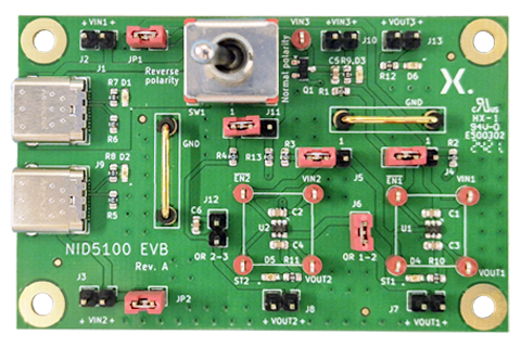
Evaluation boards
产品
| 型号 | 描述 | 状态 | 快速访问 |
|---|---|---|---|
| NID5100 | 1.2 V to 5.5 V, 1.5 A input polarity protected, low quiescent current ideal diode | ACT |
|
| NID5100GW | 1.2 V to 5.5 V, 1.5 A input polarity protected, low quiescent current ideal diode | Production | |
| NID5100GW-Q100 | 1.2 V to 5.5 V, 1.5 A input polarity protected, low quiescent current ideal diode | Production | |
| NID5100-Q100 | 1.2 V to 5.5 V, 1.5 A input polarity protected, low quiescent current ideal diode | ACT |
|
| NID5100GW-Q100 | 1.2 V to 5.5 V, 1.5 A input polarity protected, low quiescent current ideal diode | Production | |
| NID1100GV | 1.5 V to 5.5 V, 1 A, ideal diode with forward voltage blocking | Production | |
| NID1101UP | 1.5 V to 5.5 V, 1.5 A, compact ideal diode with forward voltage blocking | Qualification |
Data sheet (3) |
|||
|---|---|---|---|
| 文件名称 | 标题 | 类型 | 日期 |
| NID1100.pdf | 1.5 V to 5.5 V, 1 A, ideal diode with forward voltage blocking | Data sheet | 2025-08-26 |
| NID5100_Q100.pdf | 1.2 V to 5.5 V, 1.5 A input polarity protected, low quiescent current ideal diode | Data sheet | 2024-07-26 |
| NID5100.pdf | 1.2 V to 5.5 V, 1.5 A input polarity protected, low quiescent current ideal diode | Data sheet | 2024-07-26 |
Leaflet (1) |
|||
| 文件名称 | 标题 | 类型 | 日期 |
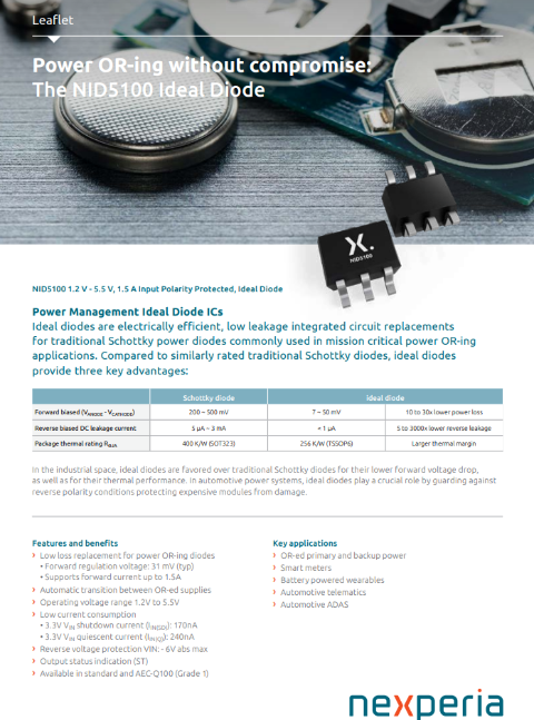
| nexperia_leaflet_ideal-diode.pdf | NID5100 Ideal Diode | Leaflet | 2024-08-09 |
Marcom graphics (1) |
|||
| 文件名称 | 标题 | 类型 | 日期 |
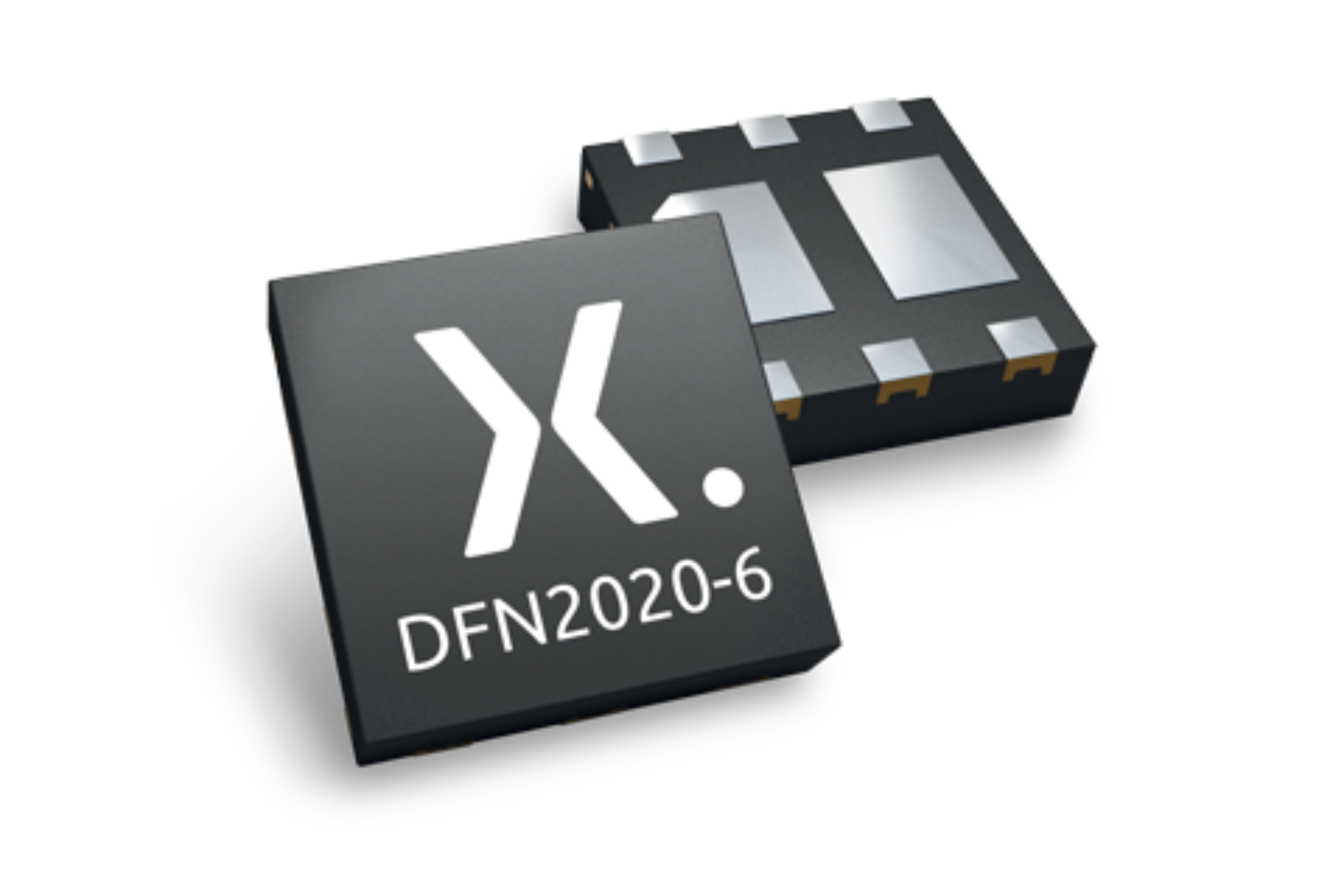
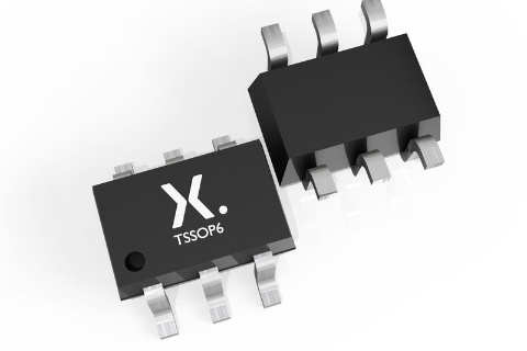
| SOT363-2_NID5100_mk.png | plastic thin shrink small outline package; 6 leads; body width 1.25 mm | Marcom graphics | 2024-07-20 |
Test circuit (1) |
|||
| 文件名称 | 标题 | 类型 | 日期 |
| aaa-042075.svg | NID1100 | Test circuit | 2025-01-17 |
User manual (1) |
|||
| 文件名称 | 标题 | 类型 | 日期 |
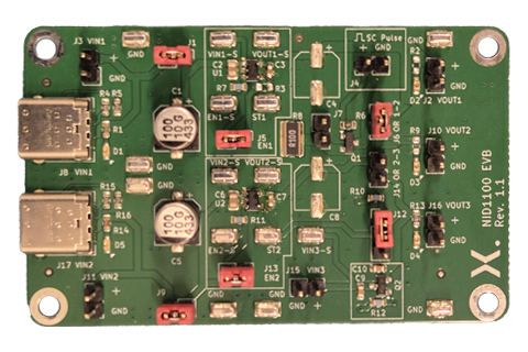
| UM90040.pdf | NID5100, 1.2 V to 5.5 V, 1.5 A input polarity protected, low quiescent current ideal diode evaluation board | User manual | 2024-07-25 |
.png)
