×

IAN50012 - Nexperia Precision Electrothermal models for Power MOSFETs

This application note introduces Nexperia precision electrothermal MOSFET models. Details are provided on how to use them in simulations and where to find them. Simulation results for key MOSFET characteristics are included.

Author: Andrei Velcescu, Applications engineer, Manchester

This interactive application note contains embedded Cloud based simulations to augment the text.

To open the embedded simulation, simply hover over the simulation image. Left click anywhere in the graphic area once the central play button changes in colour. This opens the schematic in the Cloud environment. See the interactive application note tutorial page for more details on how to use the simulations.

Download AN90034

Introduction

Nexperia provides MOSFET precision electrothermal models that link the electrical and thermal performance. The models are available in SPICE and VHDL-AMS for multiple simulation platform support. They represent all the key MOSFET behaviours relevant to MOSFET applications. As such it is possible to estimate device performance quickly and accurately within widely available simulation tools before any physical prototyping. By using the latest MOSFET models errors can be spotted and designs can be optimized for cost and performance much earlier in the design cycle and changes can be implemented timelier, thus improving time to market. This application note introduces the models, how to use them, what their capabilities and limitations are, and where to find them. The models will be available in the PartQuest Explore PartPartner Library and on our website. The simulation tool used will vary how this works e.g., LTspice™ or PSpice

Using the models

The precision electrothermal models come in two variants, downloadable LTspice ones and online VHDL-AMS.

Online on PartQuest Explore

The precision electrothermal models are available in VHLD-AMS format which is supported by PartQuest™ Explore (https://explore.partquest.com). Here, the models are available within the partner library and are ready to be used with no additional set-up. Further examples of models and simulations using PartQuest™ Explore can be found on Nexperia’s Interactive Application Notes (https://www.nexperia.com/applications/interactive-app-notes)

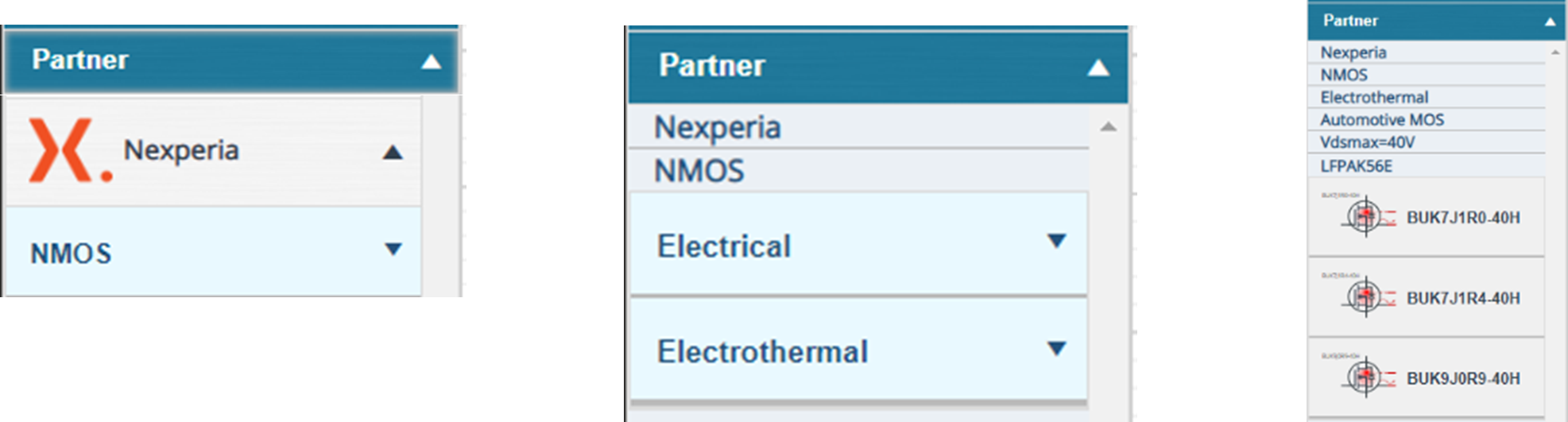
Figure 1. Nexperia Power MOSFET simulation models

Importing models in LTspice™

Download the precision electrothermal model ZIP file from Nexperia.com, e.g. BUK7xxxx-40H_LTspiceV3. The ZIP file contains the library file and symbol. Moreover, the file can be downloaded from the product page Documentation or Support tabs.

Model description

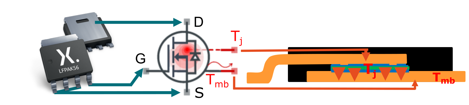
The precision electrothermal models have 5 pins, the 3 traditional electrical pins for Gate, Drain, and Source and two additional pins for interacting with the thermal properties of the MOSFET, see Fig. 2. These are namely the junction temperature pin, Tj and the mounting-base pin, Tmb. Tj can be probed and gives the junction temperature in °C. In addition, this pin can be connected to a fixed voltage source to set the junction temperature as a constant, this disables the self-heating behaviour of the model. Otherwise, it can be left open and monitored.

Figure 2. MOSFET Electrothermal model temperature pins

Tmb represents the thermal connection of the device to the outside world e.g., the heat path from the mounting base of the MOSFET to a PCB or heatsink. This pin can also be connected to a fixed voltage source, this will set the ambient temperature. In addition, thermal models of PCBs can be connected to the MOSFET Tmb pin model to simulate the system thermal performance in Simulation 1 below.

Simulation 1. MOSFET self heating

Model behaviour

The following characteristics may be modelled using the 5 pin precision electrothermal MOSFET model:

  • Gate-source threshold voltage (VGSth) as a function of junction temperature (Tj)
  • Transfer characteristics (ID as a function of VGS) vs temperature
  • RDSon as a function of VGS and temperature
  • Output characteristics (ID as a function of VDS) vs temperature
  • Diode forward characteristics (VSDS) as a function of temperature
  • Body effect, operation in 1st and 3rd quardants
  • Drain source leakage (IDSS) as a function of temperature
  • Breakdown voltage (BVDSS) as a function of temperature
  • Internal capacitances as a function of drain-source voltage
  • Gate charge (QGD) as a function of gate-source voltage
  • Diode reverse recovery (QRR)
  • Package related parameters

Where possible an example circuit is shown to demonstrate each behaviour. For each of the following examples the Tj pin will be shorted to Tmb, turning off the self-heating. Note: the characteristics are always typical values and do not represent the limits of process variation. The device used in the simulations is BUK7S1R0-40H a 40 V, 1 mΩ power MOSFET in the LFPAK88 package. It is from the Trench9 40 V Standard Level Automotive portfolio.

RDS(on)

RDSon is measured with a fixed current source typically 25 A but may be less for a smaller die. The VGS is stepped in the same manner as ID vs VGS. The simulation set-up in Simulation 2 shows the RDSon vs VGS, this can be derived by dividing the drain-source voltage (VDS) by the ID.

Simulation 2. RDSon

Package related parameters

Impedances due to the packaging are modelled, these include resistances associated with the clip and lead frame and solder interconnects etc. The package resistance also changes with temperature. Further to this the parasitic inductance is included in the model. This is critical for simulating for EMI investigations. See Simulation 3 below.

Simulation 3. Zth(j-mb)

Threshold voltage and transfer characteristic

The ID / VGS sweep fixes the VDS and sweeps the VGS, turning the MOSFET on, the resultant drain current (ID) is probed. Set-up of the ID / VGS sweep is shown in Simulation 4 which also shows the ambient temperature is stepped.

Simulation 4. Transfer characteristic

Output characteristics (ID / VDS)

Here VGS is held constant and VDS is stepped. This is repeated for different VGS values. The ID is probed. The schematic set-up and resultant waveforms are shown in Simulation 5.

Simulation 5. Output characteristics

Diode characteristics (VSDS)

MOSFETs have an anti-parallel diode within the structure, as such it conducts when the source drain voltage (VSD) reaches the forward voltage drop (VF) of the diode. This is also temperature  dependent; the diode’s VF decreases with temperature and its slope resistance increases. See Simulation 6 below.

Simulation 6.

Body effect

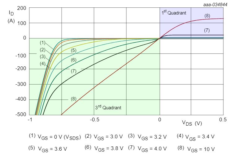
In many half-bridge applications, the MOSFET may replace the free-wheeling diode to achieve synchronous rectification. The MOSFET’s RDSon produces a lower voltage drop Drain to Source than the diode’s VF so power loss is reduced making the application more efficient. However, MOSFETs conducting current through the channel in reverse, such as in synchronous rectification, will have lower threshold voltage. This is known as the body effect and is accounted for in the models derating with negative VDS and ID. The body effect is also sometimes referred to as third quadrant operation. Fig. 3 shows both the first and third quadrant of operation. The first quadrant is ID / VD as previously shown and in the third quadrant when the VGS = 0 is the diode curve. Fig. 3 also shows operating in the third quadrant with a positive VGS and the increased ID due to the Body Effect. See simulation 7 below.

Figure 3. Full quadrant operation of a MOSFET showing ID / VD, VSDS and the Body Effect; simulation results

Simulation 7.

Drain leakage (IDSS), breakdown voltage (BVDSS) and avalanche breakdown

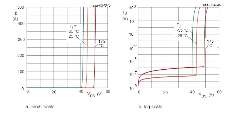
Included in the precision electrothermal models are temperature dependant drain leakage current and breakdown voltage. In addition, the slope resistance of avalanche breakdown is modelled, see Simulation 8 below. Fig. 4 shows the simulation results plotted with ID on linear and logarithmic scales.

Figure 4. Avalanche breakdown; ID as a function of VDS simulation results

Simulation 8. Drain leakage (IDSS), breakdown voltage (BVDSS) and avalanche breakdown

Capacitances and gate charge

Capacitances

The MOSFET’s internal parasitic capacitances and their voltage dependence is modelled. This is critical for accurate switching time simulations and gate charge modelling. The capacitance values have insignificant temperature dependence so in the model they are fixed with respect to temperature. The gate charge does have some temperature dependence; the Miller plateau voltage is dependent on the gain of the MOSFET which in turn is temperature dependant. See simulation 9 below.

Simulation 9. Capacitances

Gate charge

To determine the gate charge, use the relationship in Equation (1),

(Eq 1). 

the gate current IG is determined by the settings of Ig1 in the schematic set-up. See Simulation 10 below.

Simulation 10. Gate charge

Body diode reverse recovery charge (QRR)

QRR is not solely dependent on the MOSFET but on the test circuit too. Specifically, the stray inductances of the PCB are critical in determining the QRR behaviour. As such it is difficult to represent the QRR in a simulation with a great accuracy without knowing or characterising the test bench being compared to the simulation. In addition, there are two standard methods of measuring QRR that will again yield different results. The preferred method for testing QRR is the double pulse method which more closely aligns with application use cases, for example half-bridge topologies such as DC-to-DC convertors and motor drives. Further information about simulating the QRR in a double pulse set-up is detailed in Nexperia application note AN90011Fig. 5 shows an example QRR waveform. See Simulation 11 below.

Figure 5. Diode reverse recovery (QRR) simulation results

Simulation 11. Double Pulse Circuit

Comparing models to datasheets

Nexperia's precision electrothermal models are based on a scalable model that takes a trend line across the parameters and die sizes in each portfolio. This means the model represents the mean device, but the data sheet represents a typical device that may not necessarily be the mean. So, whilst the model may not match the datasheet exactly, it will always be within part-to-part variation for that parameter. In general there is good alignment between the simulations and the datasheet. A second factor where models may deviate from the datasheet is due to self-heating effects that occur on measurements.

Some measurements such as diode-forward characteristics and output characteristics generate a lot of power in the device. Whilst the measurements are taken in as short a time possible the pulse is a finite period and self-heating will always occur. See Simulation 12 below.

Simulation 12.  Self-heating

Simulations tips and tricks

Whilst we endeavour to make the precision electrothermal models as stable as possible some simulations may not converge, here are some tips and tricks:

  • When using current sources to drive the pins of the model, placing a resistor to ground from the output of the current source may help, start at 1.0E9 Ω first, and go down in decades
  • Changing the tolerances may help, decreasing the tolerances may be acceptable for power electronics simulations
  • In PartQuest Explore using the Advanced Options, i.e.: More Speed, Balanced and More Accuracy and selecting Convergence Assist often more successful in achieving convergences faster

Full simulations validity range

Characteristics Operating condition range Temperature range Comments
RDSon

VDS = -1.2 V to 8.0 V; VGS = 0 V to VGS(max)

-55 °C to 175 °C  
ID/VG VDS = 0 V to 8.0 V -55 °C to 175 °C  
ID/VD VDS = 0 V to 8.0 V -55 °C to 175 °C  
VSDS ID ≤ pulsed drain current limit (IDM) -55 °C to 175 °C  
BVDSS ID ≤ pulsed drain current limit (IDM) -55 °C to 175 °C  
QG and capacitance full data sheet voltage range -55 °C to 175 °C not temperature dependant
QRR VDS = 0.5 x VDSmax -55 °C to 175 °C not temperature dependant
Thermal impedance (Zth) NA -55 °C to 175 °C worst case value as per data sheet
IDSS VDS = 0 to BVDSS -55 °C to 175 °C  
IGSS NA NA not modelled


Summary

Nexperia's new precision electrothermal MOSFET models have been introduced and their use in PartQuest Explore simulations has been demonstrated. Precision electrothermal models will feature in future interactive application notes, please visit the Nexperia website to learn more: https://www.nexperia.com/ applications/interactive-app-notes/.

Page last updated 19 October 2023.